

| Home | S-100 Boards | History | New Boards | Software | Boards For Sale |
| Forum | Other Web Sites | Quiz | Index |
 |
 |
||
 |
|||
 |
 |
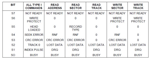
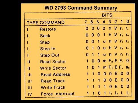
| WRITE$SECTOR: MVI C,CMD$SET$TRACK CALL S100OUT LDA @TRK MOV C,A CALL S100OUT ;Send Selected track CALL WAIT$FOR$ACK ;Return Z (and NO$ERRORS$FLAG in [A]), or NZ with error # in [A] JRNZ WRITE$ERROR MVI C,CMD$SET$SECTOR ;Sector # to side A (or for DS disks also side B) CALL S100OUT LDA @SECT INR A ;Disk sectors 1...MAXSEC MOV C,A CALL S100OUT ;Send Selected sector HEX number CALL WAIT$FOR$ACK ;Return Z (and NO$ERRORS$FLAG in [A]), or NZ with error # in [A] JRNZ WRITE$ERROR MVI C,CMD$SEEK$TRACK CALL S100OUT CALL WAIT$FOR$ACK ;Return Z (and NO$ERRORS$FLAG in [A]), or NZ with error # in [A] JRNZ WRITE$ERROR MVI C,CMD$WRITE$SECTOR ;Now send the Write Sector Command CALL S100OUT CALL WAIT$FOR$ACK ;Wait for NO$ERRORS$FLAG to come back JRNZ WRITE$ERROR LHLD @DMA ;Load up the DMA address LDED SECTOR$BYTE$COUNT ;and byte count of bytes to be sent (128,256,512 or 1024) JMP ADJ$BANK1 CSEG ;======================================= ADJ$BANK1: LDA @CBNK PUSH PSW LDA @DBNK ;Point to the databank where the data has to come from CALL ?BNKSL WR$SEC:MVI B,0FFH ;Put in a timeout count (Loop for status read at most 256 times) WR$SEC1:DJNZ WR$SEC2 POP PSW ;Need to get back to DSEG bank! CALL ?BNKSL MVI A,TIMEOUT$ERROR ;Send Timeout error JMP WRITE$ERROR ;Note we cannot use S100OUT here since we are no longer in the DSEG bank WR$SEC2:IN S100$STATUS$B ;Send data to ZFDC output (arrive with byte to be sent in M) BIT DIRECTION$BIT,A ;Is ZFDC in input mode, if not wait JRNZ WR$SEC1 BIT DATA$OUT$RDY,A ;Has previous (if any) character been read. JRZ WR$SEC1 ;Z if not yet ready MOV A,M ;Get the byte OUT S100$DATA$B ;Send it INX H ;[HL++] for [DE--] bytes in sector DCX D MOV A,E ORA D JRNZ WR$SEC POP PSW CALL ?BNKSL ;Back to the original databank JMP CHECK$WR ;Get back to DSEG ;======================================= DSEG CHECK$WR: CALL WAIT$FOR$ACK ;Return Z (and NO$ERRORS$FLAG in [A]), or NZ with error # in [A] JRNZ WRITE$ERROR RET WRITE$ERROR: LXI H,FLOPPY$WRITE$ERR ;"Sector Read Error" CALL GET$ERROR$STRING ;Get Error String from ZFDC Board JP COMMON$RW$ERROR |
|
As you can see the code is really nothing more than a few calls to the
ZFDC board. Once setup, the board will send the block of data to
the requested sector on the disk. Now what is nice about all this is
that, first, if you decide to use a different disk format you just let the ZFDC board
know with a single command (Typically at CPM Boot time, but more elaborate
BIOS'es can do so on the fly). Probably more important
however, when we
go to utilize other CPU's (CPM86, MSDOS, CPM-68K etc), it's a very
simple rewrite to do a FDC BIOS/Device driver for that system.
A
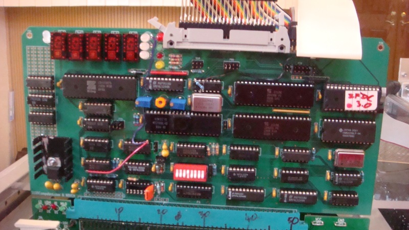
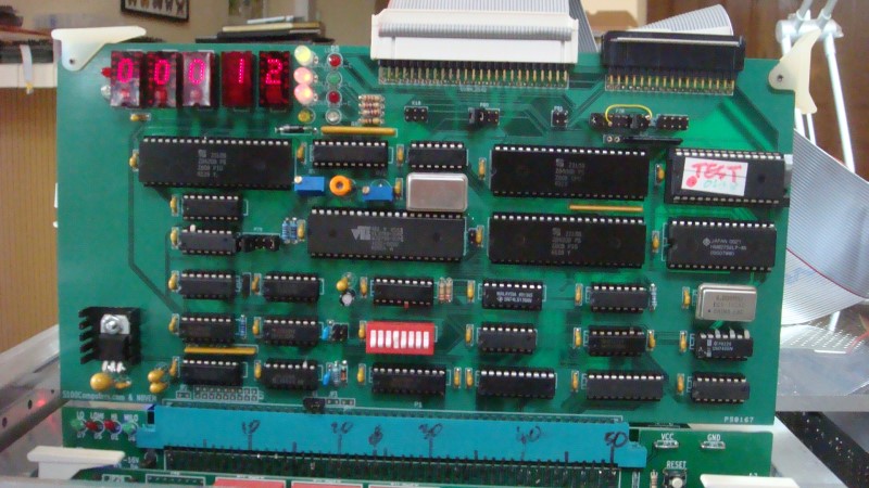
Third Prototype ZFDC Board
Based on working with the above second prototype board for a few weeks, I improved
the design and with Andrews help designed a third prototype board. Again there were many small
additions and improvements. Still more LED's to let you know what is going on.
Also better status signals being passed back to the S-100 bus for the same
reason. Also added was the capability to trigger the Z80's NMI line
based on a triggering by only the WD2793's INTRQ line. The
DRQ and timer circuit described above in the version 2 of the board were no
longer needed. Now the software on both the ZFDC and S-100 side check
for hang-ups. This is a more flexible and reliable arrangement.
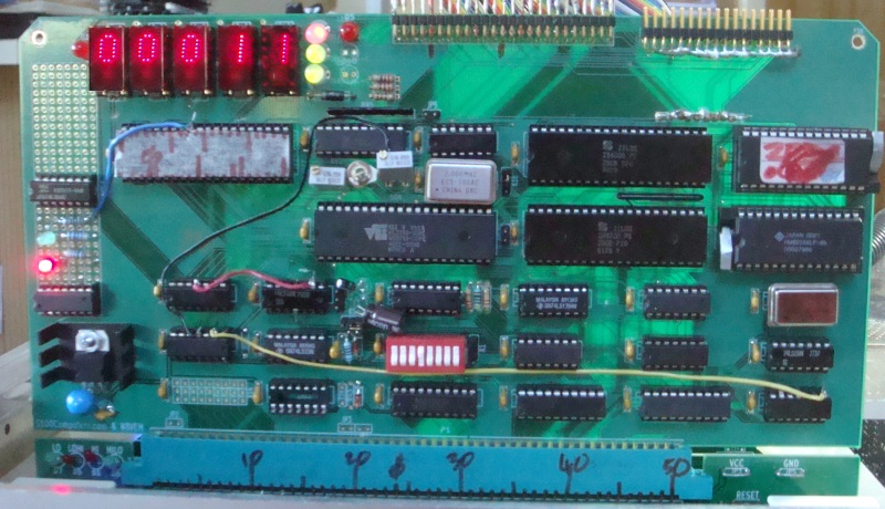
Here is a picture of this third board:-
The schematic of this board at first looks a bit overwhelming, but when you brake it down to its components its fairly easy to understand. Much of the complexity has to do with the fact that I have split out the ribbon cable connectors for 8" and 5"/3" drives so that each has their own separate jumpers and drivers. I found that terminating the drives all linked to one connector interface just did not yield reliable (5" drive) data. Not helping was the diversity of pin designations found amongst 5" & (particularly) 3" drives.
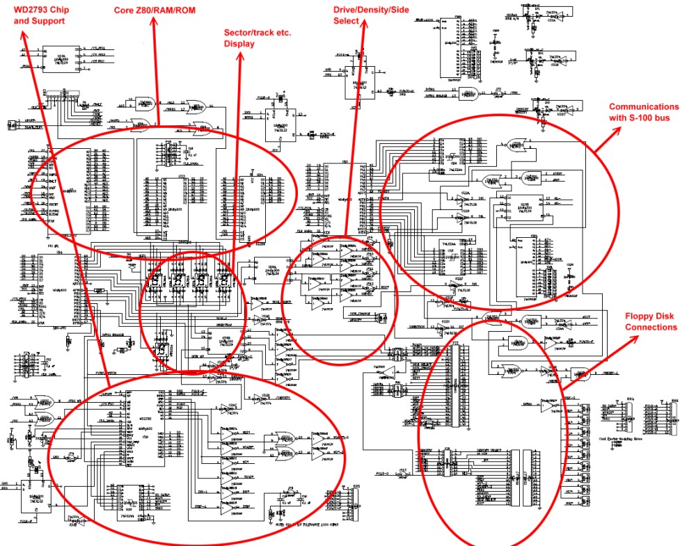
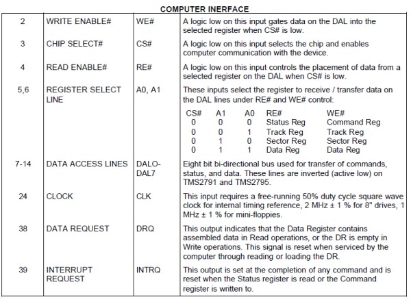
Let us look at each section in turn. The most critical actually turns out to be the interface between the S-100 bus and the ZFDC board internals. All data communications takes place through PIO#1 on the board. However it is necessary to also provide the S-100 bus side with bit flags to know if the ZFDC is ready to receive a command or data and likewise for the ZFDC board to let the S-100 bus side know it is busy or has data available. Complicating things is the fact that data to/from this PIO is interrupt driven in software. Here is a more enlarged map of this region:-
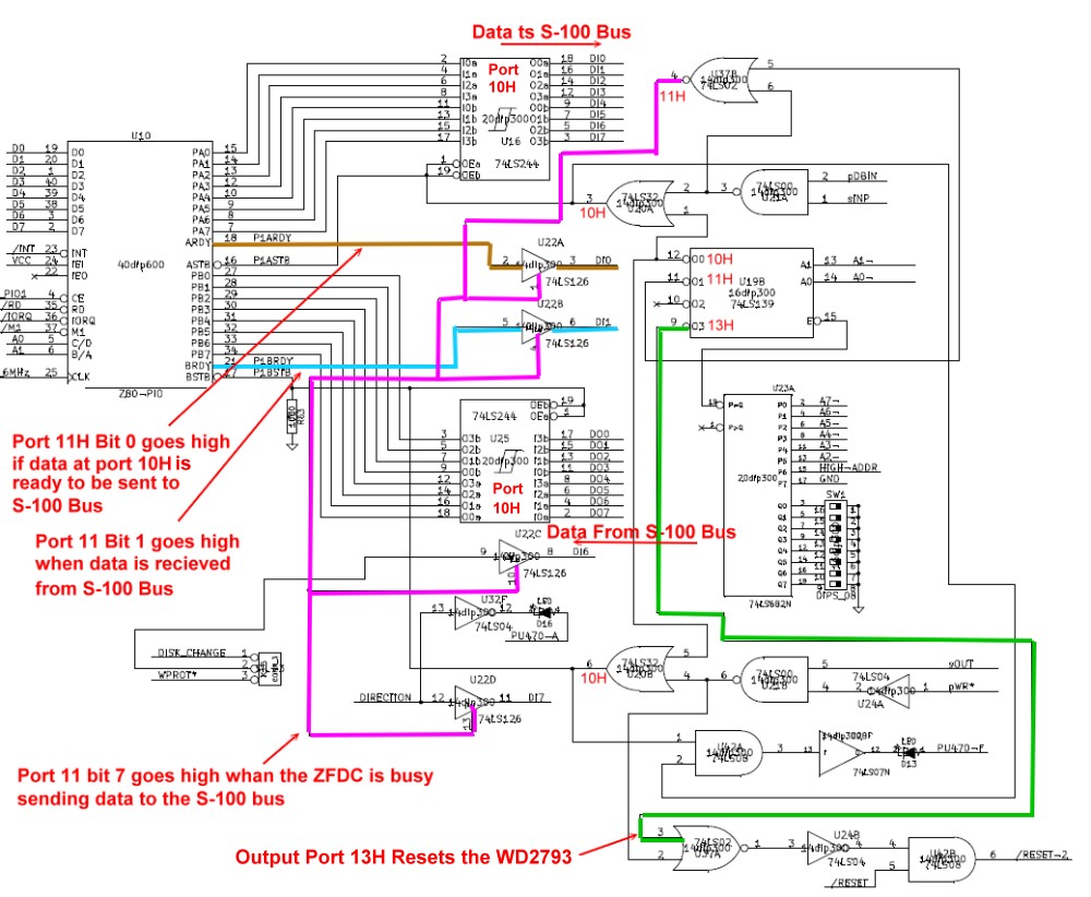
You will also note we have a third port (configured as 13H) which allows the S-100 bus to completely reset the WD2793 chip if the ZFDC board is hung or not responding. This clearly is only used in a drastic situation -- such as the board trying to read an unformatted disk etc.
The second PIO chip on the board controls the floppy disk selection and configuration pins. Here is a map of this region in more detail:-
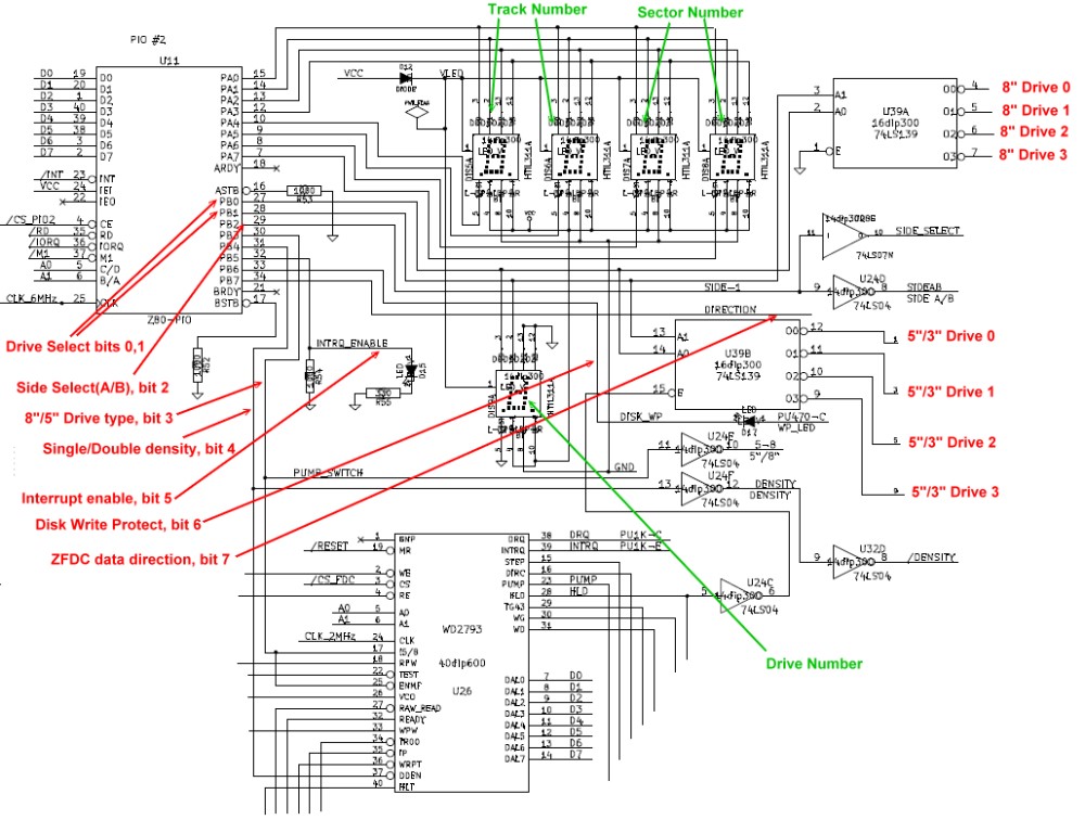
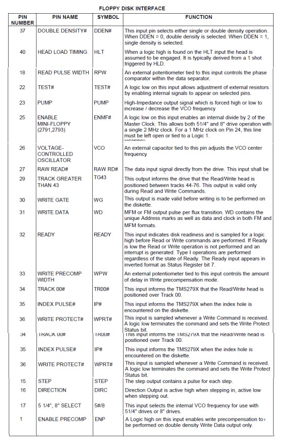
The second dual parallel port PIO (U11) has two functions. The first port, (port A), is completely devoted to displaying the current WD2793 selected disk track and sector. The second port, (port B), is a bit more complex. The lowest two bits (0 & 1) select the current floppy disk in hardware. A maximum of 4 disk drives are allowed. The two lines are de-multiplexed into 4 drive select lines by the two 74LS139's. U39A is for 8" drives, U39B is for the 5" & 3" drives. Bit 2 selects the A or B side of the selected disk. The WD2793 can work with 5" or 8" (& 3") disks in terms of data rate. However the input clock frequency needs to be adjusted. This is done via pins 17 and 25 of the WD2793. Bit 3 controls this selection, it is high for 8" disks.
The WD2793 FDC can work with single and double density disks. This is done with pin 37. This is set with bit 4 which is high for single density.
Bit 5 allows the WD2793 INTRQ (pin 39) to trigger an NMI interrupt to the boards Z80. The WD2793 triggers the INTRQ line when each chip command is completed. This allows the software to be efficiently interrupt driven for things like sector reads and writes -- (See the ZFDC.Z80 software).
Bit 6 flags whether the current disk is write protected.
Finally bit 7 provides a flag bit to essentially let the S-100 side of things know the ZFDC Z80 is still busy and not to send another command yet.
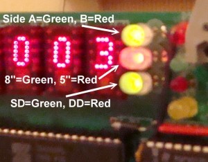 Besides the HEX displays that show the currently
selected Drive, Track and Sector, there are three dual colored
(Red/Green) LEDs. These show the currently selected drive size
5"/8", the current selected disk density (SD/DD) and the correctly
selected disk side A or B.
For a Single density, 8", Side A, disk all three LED will be green.
By looking at the HEX displays and these three dual colored LED's you can easily check the status of what the WD2793 FDC chip is expecting to see. In particular as you format different disks always make sure the LED colors match with what you would expect.
BTW, when you assemble the board make sure you have the LED's inserted the right way around. Either test each pin for color off the board or go to the board's monitor (menu # 19) and output the appropriate bits to port 06H and check for the correct Red or Green color before you solder the LED in place.
The above port bits are the first entry in each "Disk Parameters Table" in the software that drives the ZFDC onboard Z80. It is called throughout the software "HW_BYTE". Each disk format table needs to have this byte carefully set up. Note, in the tables themselves the high 3 bits are always 0's. Here again is a summary of the bit information:-

For the core Z80 CPU itself there is just a single static RAM chip and an EEPROM chip.
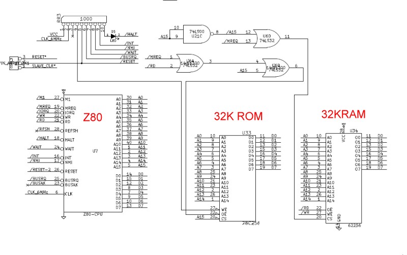
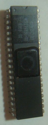
The only addressing circuitry used is address line A15 for addressing EPROM (low) or RAM (High). These three 40 pin chips along with the two 40 pin PIO's supply the complete onboard "computer" with its four 8 bit input and output ports (with handshaking). The Z80 halt line is brought out to an LED indicator to test/debug the board during construction. With just the above circuit (+6MHZ clock) and an EPROM filled with 76's, the HALT LED should light up for initial testing.
Since the Z80 runs at 6MHz, only Zilog Z80B parts should be used. These are rated for 6MHz. However I have found at least for the PIO's that older Zilog PIO's work fine. As explained above, the Z80 cannot keep up with the WD2793 data rate (particularly in DD modes) at 4MHz. I have actually run these Z80B's at 8MHz with no difficulties what so ever!
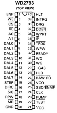
The WD2793 related circuit is fairly straightforward. All chip to disk output lines go through open collector 74LS06's. Critical input lines come back through the Schmitt triggered 74LS244's. Here is a diagram of this region of the board:-
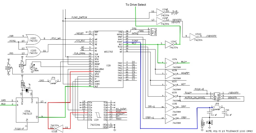
The test (pin 22), RPW (pin 18) and VCO (pin 26) must be adjusted to get the best data/clock separation for your particular setup. I explained below how to do this. The 50K pot attached to pin 33 (WPW) is used to adjust the "write pre-compensate" on some of the very early 8" drives. Most later drives take care of this themselves on the drive. If your drive need this adjusted see the WD spec sheet and/or your drive manual. Failing that, just set the ZFDCDIAG.Z80 program to repeatedly read/write sectors and tweak the RV2 pot settings by hand until you get no errors.
One pin I was worried about was the "pump" pin (pin23). Input from this pin comes from a resistor/capacitor circuit that controllers the voltage controlled oscillator (VCO) within the WD2793 chip. Western digital had 0.1uF for 8" drives and 0.2uF for 5" drives. originally I had an analogue switch for each input depending on the drive being accessed. It seems not to be critical. I use 0.1uF for both drive types. However if you are mainly using 5" drives then install jumper JP8.
The Head Load pin (pin 28) serves two functions. First it AND'ed with each of the drive select pins so that the head is only loaded on the currently selected drive, however it also triggers the 74LS123 (U35A) so that the WD2793 is delayed a little (via the HLT pin 40) to allow the head to settle down before actually reading or writing data.
Here is a short video demonstrating this board in action and a brief display of some of the ZFDCDIAG menu items.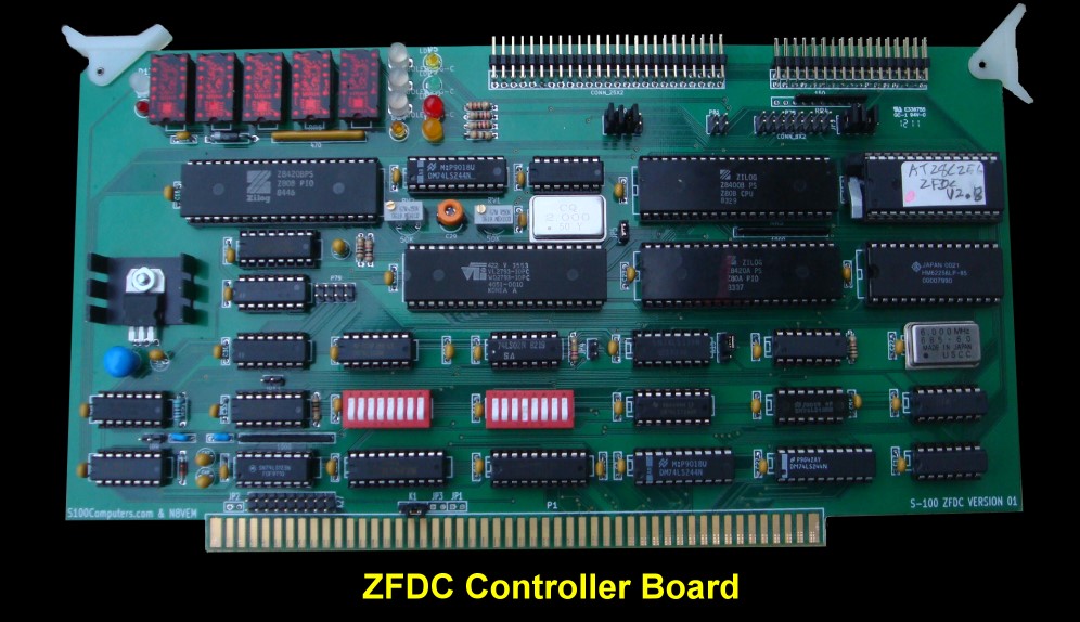
That said, the board is a real joy to work with. Because the BIOS command control is so simple, writing disk drivers for CPM+, CPM86, DOS etc is real easy. As we develop 16 bit S-100 boards we will try and bring this board along with these systems.
Finally I would like to ask others to provide more extensive software for the board. I have written a fairly well documented on board Monitor/BIOS, a menu driven CPM based diagnostic program and a separate CPM based disk format program. Additions, improvements etc. are welcome.
I have written both banked and non-banked versions of CPM3 for this FDC board. It is extensively written up in the software section of this site. Please click here for more information.Building Board - Step by Step Instructions.
First inspect the board for scratches or cut traces. Insert all IC sockets, Caps, resistors, the two clock generators (2MHz & 6MHz), resistor networks, the voltage regulator and jumper pins. I like to solder clock generators directly to the board. If you do use a socket be sure the thin wires make good contact and/or use the special sockets for these "chips". Also make sure to position pin 1 correctly. Take care to get the polarity of caps correct. The square pad is the positive side. Also note that the resistor network RR4 has pin 1 on the right hand side. Test the empty board for +5 volts on all the empty IC sockets.
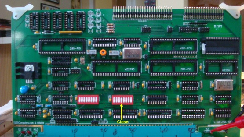
Install Jumper K1 (for board reset, bottom of board) to 2-3 position. Install IC's U21 (74LS00), U23 & U45 (74LS682), U42 (74LS08), U20 (74LS32), U24 (74LS04), U32 (74LS04), U28 (74LS07) U37 (74LS02) and U19 (74LS139). Next install the 8 position dip switches SW1 & SW2. We will use S-100 I/O ports 10-13H so all switches are close except switch 5 (counting right to left). Here is a picture:-
Go to your monitor and at 0H in RAM enter
DB, 10, C3, 00, 00
Jump to 0H in RAM. This will have your Z80 continuously input from port 10H. Check with a logic probe pin 12 of U19 pulses low. Then check that pin 1 of empty socket U16 pulses low .
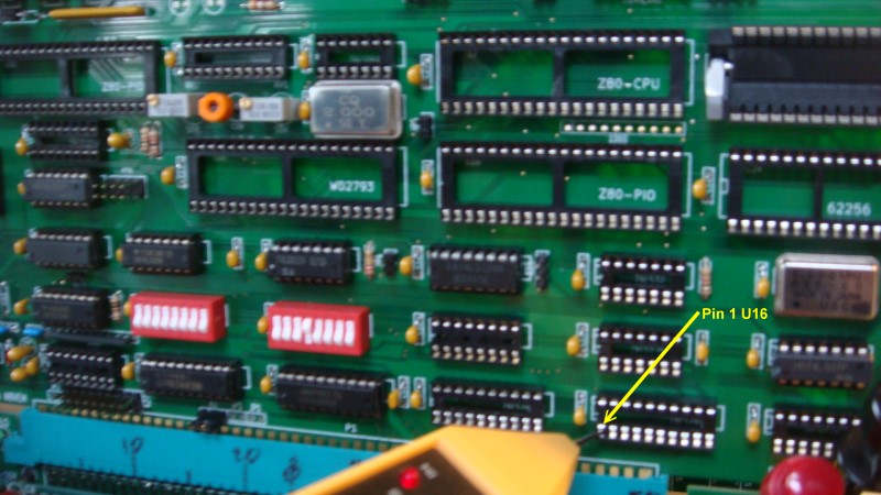
Next change the above code to:-
D3, 10, C3, 00, 00
Check pin 1 of empty socket U25 pulses low:-
Then change the code to:-
D3, 13, C3, 00, 00
Check that pin 6 of U42 pulses low.
Now go back and insert the code
DB, 10, C3, 00, 00
Insert the Diode D13 (I use a blue LED, initially just hold it in place) and test the code. The diode should light up (if you have it in the right way). Test also:-
D3, 10, C3, 00, 00
If OK, solder the diode in. Make sure ports 11H,12, and 13H do not light up the diode.
Insert U16 & U25 (74LS244's) and U22 (74LS126).
Temporally jumper pin 2 of K15 to ground. Input port 11H. You should see 10111111B. Remove the jumper.
You now have the S-100 communication side of the board done!
Next we will insert the Z80 onboard RAM & EEPROM circuitry.
Insert U7 (Z80B), U11 & U10 (Z80B PIO's), U34 (SRAM, HM62256LP), U33 (EEPROM 28C256) and U6 (74LS32).
Insert the diode D5 and program an EEPROM with all 76H's (HALT, Z80 opcodes). Insert and power up the system. After reset (each time) and a slight delay the LED should light up. Do not go further until you get this to work. The Z80 must be able to access the onboard EEPROM (at 0H) and see that the first opcode is a HALT (76H) instruction. Here is what you should see:-

Before you solder D5 in you can use the two holes to get the orientation of the 4 other LED's nearby. Pick different colors for each LED. Each in position D5 should light up. Then solder all LED into positions (D5, D9, D10 ,D15). For most LED's the longer LED lead goes into the square pad. Also add LED D16.
Next insert (only one, they are expensive!)) a TIL 311A HEX LED display in position DIS9. On power up it should display "3". If it does insert the rest of the TIL's. Here is a picture of the board so far:-

Then download the ZFDC.HEX file software (here) and program an 28C256 EEPROM with it (Note more recent versions of this software may exist in the future. See the bottom of this page). There are many ways to do this and many programmers available. I particularly like the Wellon VP280. It's Windows 7 compatible and easy to use. I am currently using ATMEL AT28C256 EEPROMS (from Jameco).
Again power up. This time the HALT LED should NOT light up. The leftmost two HEX displays will continuously count 0 to FFH. The other TIL's should display 0's. Here is a picture of the board so far:-
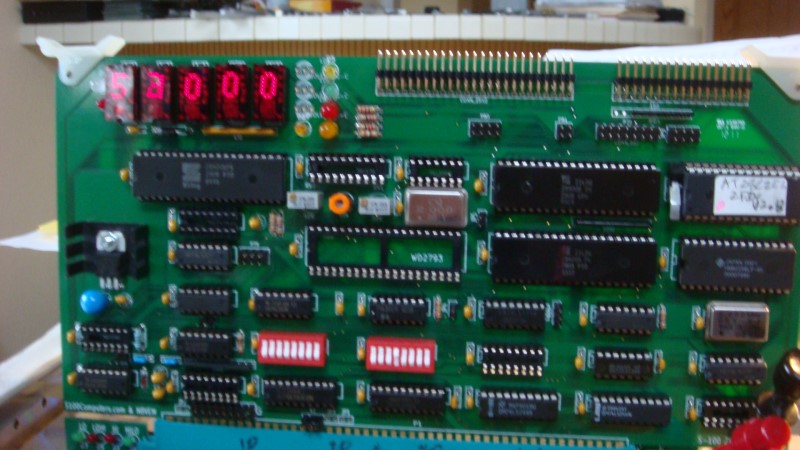
This is the normal startup mode of the board indicating it is ready to be initialized and accept commands from the S-100 system. If you get this far you now have a functional Z80 "computer" working on the board. While you should not need to do so, the HEX display was invaluable for me to initially debug the board. You can put up increasing numbers as you step through your software/hardware development.
Next install all remaining IC's including the WD2793 chip. Install jumper JP5.
Again power up your system. You will next need to carefully install the dual color LED's LD1, LD2 and LD3. Orientate the 3 LED pins so the top LED is red, and the bottom two are green. Carefully solder into place.
The remaining board jumpers are dependent on the size and type of floppy disks you will be using.
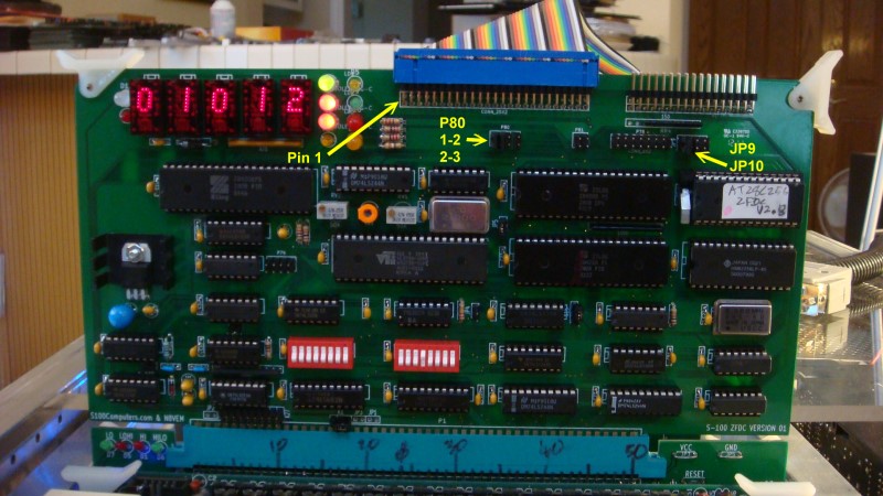
Assume for now we have two 8" drives as A: & B:, So jumper JP9 1-2 and JP10 1-2. Jumper P80 1-2 & 2-3.
Connect up the floppy disk ribbon cable connector making sure pin 1 is towards the front of the board on the left hand side
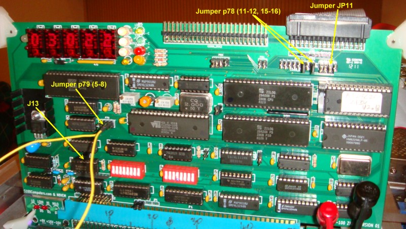
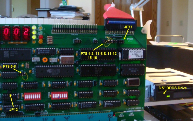
Here is a picture of the completed board. Note some drives require different jumpers. For example some require jumpers on p79 to start the drive motor. You will need to experiment quite a bit.
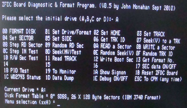
Next launch the S-100/CPM based diagnostic program ZFDCDIAG mentioned above.
Here is it's signon screen:-
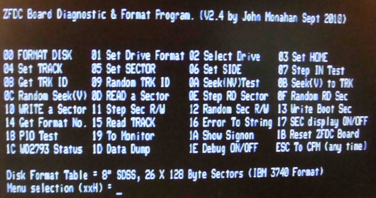
It will come up assuming you are using an 8" disk in drive A: Your first test should be Menu #07. This will repeatedly step the head in one track at a time. It is independent of many disk (and WD2793) parameters. If it does not work, check your drive jumper connections. Next try Menu #0A. It should do the same thing.
If you have drive problems "stepping the head" chances are you do not have either the board jumpers correct or your connections to the drive itself are not configured correctly. I use a "gerry rigged" jumper shown here to narrow issues like this down with different drives.
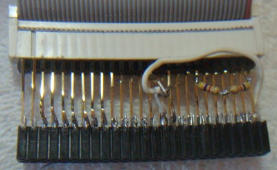
It's not a pretty sight but you only use it when needed. For 8" IBM formatted drives the following pins need to be connected:-
Pins 4 & 14 need to be tied high (to 5V through 470 ohm resistors) and to +5V on the board via a temporary wire jumper.
Pins 18, 22, and 26 are tied to ground.
Pins 20, 34, 36, 38, 40, 42, 44 and 46 are connected to the drive cable. All other connections are left open. With this "connector" you should be able to step, read and write to the disk is drive A:
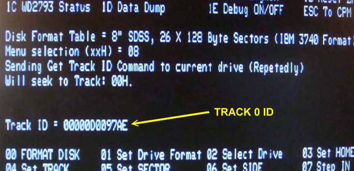
Then assuming you have a formatted disk, try Menu #08. This will give you the Track ID. For Track 0 of an 8" Single density disk you will get something like this (depending on the sector the head lands on, see above):-
You can then use most of the commands to test your disk/zfdc controller system. It should work 100% reliable on a properly formatted disk. Do not even think of using the controller in a CPM system if this is not the case. Also include in the software below is a program to format a disk (8" & 5" disks, most common formats). The is also a simple program to quickly copy one disk to another.
Adjusting the Data Separator setting of the WD2793.
One thing that often scares people away from these early FDC chips is the
need to fine tune the data separator/analogue signal of the raw data coming
in from the disk. I have found that the WD2793 works with almost
any setting for 8" single density drives. Not so for the double density 5"
floppy disks however. Early FDC boards often had elaborate hardware
that sometimes required careful adjustment to get a reliable signal,
particularly for Double Density modes. Western Digital greatly
simplified this process with the WD2793 chip. All that is required is one
50K Potentiometer and a 5-50pF variable capacitor. The
adjustment process is as follows:-
Reset the WD2793 chip (Reset on the S-100 system).
Bring up CPM and load the ZFDDIAG program.
Start the boards Monitor program (Menu #19).
Output 08H to Port 06H (PIO#2B, U11). Use
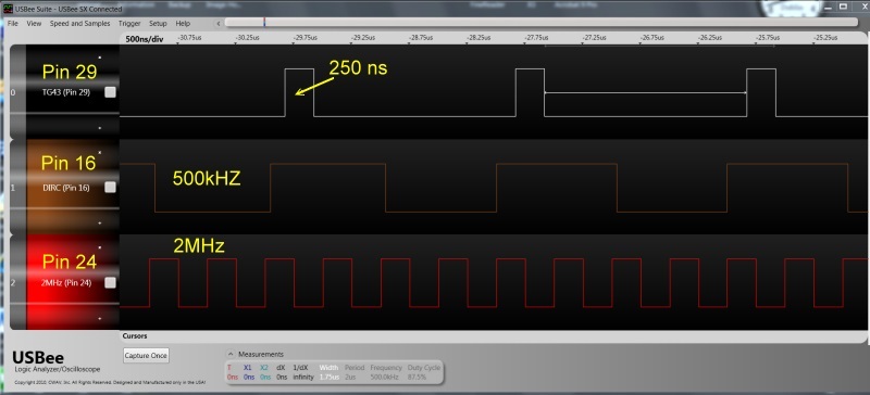
With the above optimization you should be able to read and write sectors to a disk with no errors. Checkout menu #12 and allow the ZFDC board to randomly read and write sectors for at least 5 minutes. No errors should be encountered.
Next use the Menu #1 and Menu#0 to change the disk format to a double density disk and format it in that density. Repeat the above steps. Then try your drive B: and if you have one a 5" drive.
After you have incorporated the BIOS in your disk operating system thoroughly check things out by copying files from one disk to another (preferably of different densities and sizes). Use the CPM "V" option to check the copy went without errors.
I have written both banked and non-banked versions of CPM3 for this FDC board. It is extensively written up in the software section of this site. Please click here for more information.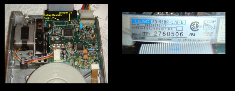
This page was last modified on 09/18/2011